Abstract Here we explain the various types of pumps in LC
LevelBasic
Two types of pumps are used in HPLC:
- Constant volume flow pumps
- Syringe type pump
- Reciprocating plunger pumps
- Reciprocating diaphragm pumps
- Constant pressure pumps
- Pneumatic pressure pump
- Column packing pump
Of these two types, constant flow pumps are most frequently used.
Since HPLC pressures are very high, the requirements for HPLC pumps are often extreme:
- Pump components should be chemically resistant to a large number of liquids, e.g. corrosive buffers
- The flow must be adjustable in steps of 0.01 ml/min in a range of 0 - 10 ml/min.
- Variations in pressure, caused by fast fluctuations in the volume flow, should not exceed 0.5%.
- The accuracy and repeatability of the liquid flow must be within 0.5%.
- The seals must be leak-proof up to 400 bar.
- The void volume of the pump chamber (or pump chambers) must be small (< 100 µl).
- There should be a safety device for leakage (minimum pressure setting) and for blockage (maximum pressure setting).
A single stroke piston pump (the syringe type) is the simplest example of a constant volume flow pump. A tighly fitting piston moves in the cylinder at a constant flow without pressure fluctuations. The cylinder also serves as a solvent reservoir. Thus, the flow must be stopped temporarily to refill the pump when the cylinder is exhausted. This type of pump is suitable for analyses requiring extremely sensitive detectors or very low flow rates. The reservoir volume is typically less than 500 ml. Though simple, such pumps are still used in micro- and nano HPLC systems for (ultra) narrow-bore HPLC columns.
Constant flow pump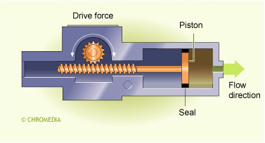
The reciprocating piston pump is another example of a constant flow pump. The animation shows the operating principle.
The synthetic seals of a reciprocating piston pump are constructed in such a way that application of pressure to liquid in the pump head results in complete sealing. When the piston moves away from the pump chamber, the underpressure closes the outlet check valve and draws solvent in through the opened inlet check valve. As the piston begins to return to the cylinder, the increased pressure closes the inlet check valve and forces solvent out through the now opened outlet check valve. The same concept applies for pumps with two pistons in series. All reciprocating pumps produce pressure pulses at least once per piston stroke.
Some pumps employ two parallel pistons which are driven by one motor, as in the above illustration. With two pistons there is a pressure impulse twice per cycle. With a carefully engineered stroke, however, parallel piston pumps can reduce the pressure variation associated with the individual piston's return stroke.
Reciprocating dual piston pump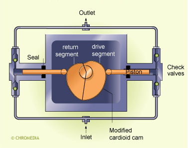
Serial dual piston pump
More recent designs have connected two pistons in series.
Piston 1 draws the solvent from the reservoir and has a considerably larger volume than piston 2. Piston 1 acts as a dynamic reservoir, whereas piston 2 (the working plunger) delivers the pressure to the column. Precise control of the stepping motor speed is very important. The pistons are driven separately so that they precisely compensate for each others movements. An electronic control circuit also measures and calculates the compressibility of the solvents. These pumps provide a very constant flow.
Pumps employing reciprocating pistons create pressure impulses during each piston cycle. A pulse dampener is required to smooth out the pulsations in the pressure profile.
A pneumatic pump is a constant pressure pump driven by an increase in the inlet gas pressure. The driving rod is attached to a large diameter piston in the gas chamber and a small diameter piston in the pump chamber. The surface area ratio of the large piston to the small piston is generally about 150/1. Thus, a low inlet pressure of 7 - 10 bar can generate outlet pressures of 1000 bar or more.
Large volume flow rates at high pressures are typical for these pumps. Flows on the order of 400 ml/min at 1000 bar are possible. As a result, pneumatic pumps are often used to pack the column with a suspension of stationary phase during column manufacture .
Diaphragm pumps work similarly to reciprocating piston pumps, except that the seals are not in contact with potentially corrosive mobile phase.
Diaphragm pump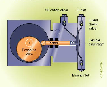
In this case the piston reciprocates in an oil chamber which is in direct contact with a flexible stainless steel membrane. This membrane forms one wall of the check valve-equipped pumping chamber. The piston is forced into the closed oil compartment, displacing a certain volume of oil, which flexes the membrane. The displacement of the diaphragm, in turn, displaces liquid from the pump chamber. When the piston moves backward, the diaphragm relaxes, creating an underpressure in the pump chamber and drawing in solvent for the next stroke. In general, the volume of a diaphragm pump chamber is larger than the volume of a normal reciprocating pump.