LevelBasic
Often problems in the HPLC‑instrumentation are related to the pump section. Logic, because the pump is a ![]() typical mechanical part and subject to wear and tear. More instrumental details on pumps and how they work can be found in the Topic on pumps.
typical mechanical part and subject to wear and tear. More instrumental details on pumps and how they work can be found in the Topic on pumps.
A malfunctioning pump often provides less or ![]() instable flow with the following symptoms:
instable flow with the following symptoms:
- Unstable retentions
- Often a lower pressure
- Irregular baseline, fluctuating, drift, spikes
- Pulsating flow/pressure
- Insufficient eluens intake from the supply bottles
- Air
 bubbles
One of the best ways to avoid problems with the pumps is to read the manual thoroughly and to apply it as well. It offers many useful guidelines regarding start‑up, normal use, maintenance and trouble shooting.
Reciprocating piston pumps are the most widely used pump systems, usually as a multiple piston pump. Important parts of the pump which are subject to wear and tear, or which are disturbance‑sensitive are:
- Plunger and seal(s),
- Inlet filter
- Check
 valves.
Contaminants can damage the plunger in the pump head resulting in internal leaks and an erratic flow rate.
- Solids such as minute flakes, dust particles, metal particles or crystallized salts from buffers hinder the sealing between the pellet and the seating of the check valve. This can damage the valve.
Trouble with pumps can be avoided by carefully ![]() filtering the mobile phase. Often a filter is built in at the inlet side of the pump. Its area is limited and the porosity will rapidly decrease when the mobile phase is contaminated and the pump will not be able to draw in sufficient eluent to maintain the flow desired.
filtering the mobile phase. Often a filter is built in at the inlet side of the pump. Its area is limited and the porosity will rapidly decrease when the mobile phase is contaminated and the pump will not be able to draw in sufficient eluent to maintain the flow desired.
A common cause of pump failure is an air bubbles trapped inside one of the check valves. Then only one of the pump heads in a dual reciprocating pump will operate and the delivery of eluent either stops completely or a flow is delivered by the pump but then the pulse damping capacity of the pump is hindered resulting in a fluctuating base line.
Air bubbles may be caused by:
- Insufficient degassing of the eluens
- Air/ clogging in the solvent filter
- Sucking helium from the degafsing unit
- An eluens with a low boling point
- Reservoir is below the pump level. (under pressure)
- Insufficient de-airing in the solvent bottle onvoldoende
- Leak in the connection of the liquid tube
- Bad mixing of the liquids
- Insufficient liquid in the bottle
Air bubbles are often formed when the pump is started up or when the mobile phase is changed. An HPLC‑pump does not, in general, have the capability to start up by itself. Usually it needs a slight under pressure on the inlet side to guarantee the flow and to prevent the formation of air bubbles during the suction stroke of the plunger. This can be achieved by raising the eluent above the level of the pump heads. Partially blocked filters can also hinder the supply of eluent.
Removing air from the pump:
- When starting up an HPLC‑instrument or when the eluent is changed, the pump can be purged with eluent by opening the purge valve directly behind the pump. The system can then be flushed at high flow rate. Take care that during flushing no air comes in through the supply line.
- However, if there is no such valve the column must be disconnected and the whole system, including the valve, can be flushed. This procedure can also be followed when air bubbles are trapped inside the
 pump.
pump. - If, after applying the above procedure there is still air in the system, the supply line to the upper check valve should be disconnected or even the complete check valve must be removed. In the majority of cases a moderate flow rate is sufficient to remove any remaining air bubbles.
- Be sure that no air is introduced through the supply line when the system is rinsed.
- If the pump is completely filled with air, it can be purged with the help of a well fitting syringe while the pump is running.
The second most common problem with pumps is a malfunctioning check valve. The symptoms observed are similar as when air bubbles are present, which means:
- No flow, or too low and strongly pulsating flow.
The problem, however, is not easy to trace. For example, it is ![]() hard to find out which of the two check valves, the upper one or the lower one, is leaking. However, this can be checked by simultaneously registering the pressure and the movement of the plungers.
hard to find out which of the two check valves, the upper one or the lower one, is leaking. However, this can be checked by simultaneously registering the pressure and the movement of the plungers.
The replaced valve should be cleaned in e.g. THF in an ultrasonic bath. In some cases concentrated ![]() nitric acid may be necessary. Write down or draw the order in which the several parts of the check valve are arranged and record any differences between inlet and outlet valves.
nitric acid may be necessary. Write down or draw the order in which the several parts of the check valve are arranged and record any differences between inlet and outlet valves.
Check valve or air bubbles in pump?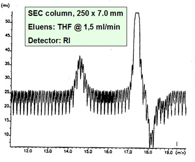
The cause of failure of valves is often pollution or buffers. When buffers / salt solutions are used the pump has to run during the night at a low flow rate to prevent problems. When the pump is not used for a longer period of time the buffered eluent must also be removed from the total HPLC system.
Always read the manual carefully!
The plunger seals are also subject to wear and tear. Worn‑out seals cause an irregular flow rate followed by leaking pump heads. It is recommended to have a spare set of seals available.
- Always follow the instructions in the manual when the seals are to be replaced. Removing the pump head should also be done very carefully. Torsion or a-centric dismantling has to be avoided to prevent the glass or sapphire plungers to break. Replacing these plungers is a job for a service engineer. Always take care to mount the new seals in exactly the same way as the old ones.
- Generally pump seals should be replaced roughly each year. The lifetime of a seal is strongly affected by the nature of the eluent and buffer. For example, the presence of dichloromethane lowers the life time of a seal significantly. Also the crystallization of the buffer makes a seal wear out quickly.
This paragraph focuses on the basics of troubleshooting. More on gradient system can be found in:
- Gradient Elution Topic
- Instrumentation for gradient elution
- Gradient elution troubleshooting and performance test.
An unstable gradient or mixing expresses itself in:
- badly reproducible retention times
- broad peaks (sometimes)
- unstable or drifting base‑line
which are due to non‑reproducible changes of the UV‑transmittance and/or elution strength of the mobile phase.
A distinction is made between low pressure and high pressure gradient HPLC pump systems:
- In low pressure mixing two or more liquids are mixed at the inlet side of the pump by electro‑magnetic valves.
- High pressure mixing uses two pumps and usually each pump supplies a pure solvent. The solvents are then mixed at high pressure to give a constant combined flow rate.
Both systems are subject to the formation of air bubbles during mixing:
- In low pressure mixing systems the most likely source of air bubbles is in the low pressure mixing chamber and these bubbles then cause problems in the pump head. Low pressure mixing systems usually need a continuous degassing with helium.
- For both types of systems the solvents need to be degassed thoroughly.
Mixing water and methanol can cause particular problems because of the heat of mixing and air volume contraction, and viscosity changes.![]() There is a good test for the quality of the gradient system.
There is a good test for the quality of the gradient system.
Every gradient system contains a certain dead volume, also called dwell volume. This is due to the volume of pump heads, mixing chamber, tubing, pulse damper, pressure gauge, etc. This is also called the system dwell volume. Consequently, there is a finite time before the actual gradient reaches the column. This time (breakthrough time) is equal to the total dead volume divided by the flow rate in ml/min.
By making a direct connection between the injection valve and the detector you can check the performance of the gradient system and determine its breakthrough time. As the dwell volume of every system is different and the breakthrough time is dependent on the flow rate, gradient times and conditions must be taken into account, particularly when using different instruments.
Performance test showing unreliable mixing.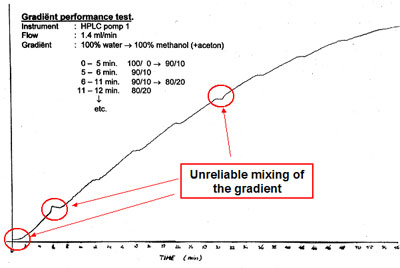 Very view gradient systems are able to pump and mix low concentrations (< 5%) of one
 ![]() liquid in another in reliable and reproducible way. If a gradient has to be started up at a ratio of 5/95 = A/B or end with 95/5 then it is better to premix these ratios and pump these as solvents mixtures A and/or B.
liquid in another in reliable and reproducible way. If a gradient has to be started up at a ratio of 5/95 = A/B or end with 95/5 then it is better to premix these ratios and pump these as solvents mixtures A and/or B.
The problems of mixing pure methanol and water can be avoided in a gradient system by premixing the solvent ![]() composition required for the start situation and use this solvent as solvent A. Condition the column after every gradient run with this solvent composition. The gradient runs in this case from a 100% A to a calculated percentage B. When the final eluent in the gradient contains a small percentage of water (e.g. 95/5) making this final eluent composition beforehand is also preferred. In this case the gradient runs from a 100% A to a 100% B.
composition required for the start situation and use this solvent as solvent A. Condition the column after every gradient run with this solvent composition. The gradient runs in this case from a 100% A to a calculated percentage B. When the final eluent in the gradient contains a small percentage of water (e.g. 95/5) making this final eluent composition beforehand is also preferred. In this case the gradient runs from a 100% A to a 100% B.
Problem caused by insufficient mixing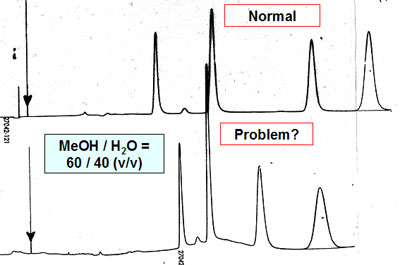
![]()